
Patent information
Regarding activities that connect creations of unsurpassed value to patents.
Through our Hyper polymer products, Junkosha continues to create and deliver unsurpassed value to our customers.We have made the fruits of such value creations into patents certainly. On the below list are recently granted patents in Japan.
Please see our unique technologies to meet customer's trust.
Speed-up of Patents Granted
As to 10 patents which were recently granted, it took 2.9 years on average before the patents issued (It took 6.5 years, six years ago).Therefore, about 40% of the total granted patents of Junkosha, has become granted in the last five years.
| Pat.No. | Issue date File date |
Title of invention | Abstract | Representative figure |
|---|---|---|---|---|
| 5935054 | 15-Jun-2016 1-Sep-2015 |
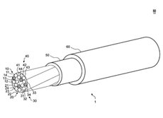
MULTI-CORE CABLE AND PRODUCTION METHOD THEREFOR | [Problem] To provide a multi-core cable wherein the positions of a plurality of insulated conductors and a plurality of non-insulated conductors in a cross section are changed along the length direction and the risk of a decrease in transmission performance is low. [Solution] The multi-core cable 1 comprises n conductor bundles 10 to 40. Each of the n conductor bundles 10 to 40 has at least one insulated conductor 11 to 13 and at least one non-insulated conductor 14. The frequency of occurrence of an identical surface in a cross section perpendicular to the length direction is AF(N) (N = 1 to n) per unit length, at least one AF(N) (N = 1 to n) being different from the others. The ratio of the number of insulated conductors to the number of non-insulated conductors in each of the n conductor bundles is in the range of 2:3 to 4:1. A non-insulated conductor to be paired with an insulated conductor is not fixed, and each insulated conductor becomes paired with a non-insulated conductor from the same conductor bundle and/or a non-insulated conductor from a different conductor bundle. |
 |
| 5935051 | 15-Jun-2016 5-Nov-2014 |
Fluororesin tube | To provide a fluororesin tube having excellent characteristics such as the heat resistance, weather resistance, chemical resistance, peeling properties, and low dielectric properties that are specific to fluororesins in addition to having an inner surface that has high adhesiveness with respect to various materials, especially silicone rubber. A fluororesin tube in which vinylalkoxysilane is introduced into a plasma excitation gas, the inner surface of the tube is subjected to plasma treatment, and the arithmetic average roughness Ra of the inner surface of the tube that has been subjected to plasma treatment and the average length RSm of a roughness curve element satisfy Ra < 0.08 [mu]m and RSm < 25 [mu]m. |  |
| 5839310 | 6-Jan-2016 16-Mar-2015 |
THERMALLY SHRINKABLE TUBE HAVING TEARABILITY | The present disclosure relates to a thermally shrinkable tube having tearability, which is made of a fluororesin, and particularly, to a thermally shrinkable tube having excellent tear straightness. Further, the present disclosure relates to a tube having high thermal shrinkage rate at low temperature. A tube including at least a fluororesin as a base resin, in which the thickness of the entanglement unit of a polymer observed on a cross-section in a longitudinal direction of the tube after being shrunk at 200°C by 35% or more is 1 μm to 9 μm, has excellent tear straightness. | 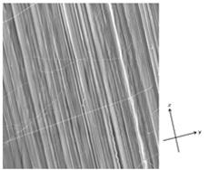 |
5779811 | 16-Sep-2015 20-Nov-2013 |
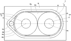
COMPOSITE CABLE | [PROBLEM TO BE SOLVED] To provide a composite cable capable of obtaining plasticity and flexibility while obtaining quality stability as the whole of the composite cable capable of inserting an optical fiber or returning a fluid for cooling and having a tube and cables, such as a plurality of signal lines and source lines inside a jacket, in a field of medical equipment. [Solution] A composite cable 1 has a tube 2 and a plurality of cables 7 inside a jacket 4. The tube has wholly or partially a layer consisting of a porous polytetrafluoroethylene (ePTFE), has a (D-d)/D of 0.27-0.75 when the outer diameter of the layer of the tube is (D) and the inner diameter is (d) and has a predetermined porous structure in which the average crevasse width of a porous structure in the ePTFE is within a region formed by connecting the four points of two points having the minimum of 10.0 μm and the maximum of 20.0 μm when (D-d)/D is 0.27 and two points having the minimum of 16.0 μm and the maximum of 27.0 μm when (D-d)/D is 0.75. |
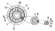 |
| 5747207 | 8-Jul-2015 5-Dec-2013 |
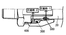
PIPE JOINT | [PROBLEM TO BE SOLVED] To provide a pipe joint capable of achieving high sealability and obtaining sufficient durability even under a structural temperature cycle environment. [SOLUTION] A pipe joint includes a joint body, a cap nut, and an approximately cylindrical sleeve fitted into the cap nut, and has an insert groove 108 to which a tip of the pipe body 20 is inserted, between a pipe body mounting portion of the joint body and a male screw portion. An approximately ring-shaped elastic body 400 corresponding to a tip-side end face 300a of the sleeve, is disposed in the insert groove 108. When the male screw portion of the joint body and a female screw portion of the cap nut are engaged, the tip-side end face 300a of the sleeve is brought into contact with one end face 400a in the axial direction, of the elastic body 400 and compresses the elastic body 400, so that the elastic body 400 presses the tip-side end face 300a of the sleeve in the axial direction by self-repulsive force. Thus a basic end-side inner peripheral face of the sleeve compresses the pipe body 20 in the radial direction through reaction force received by a fitting face of the cap nut. |
 |
| 5747206 | 8-Jul-2015 31-Aug-2010 |
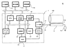
LEAKAGE DETECTION DEVICE OF LIQUID TRANSPORT PIPELINE AND METHOD FOR THE SAME | PROBLEM TO BE SOLVED To provide a leakage detection device capable of reducing processing time. SOLUTION A leakage detection device of the present invention comprises: a leakage detection cable 11 which is laid down along a pipeline and changes characteristic impedance thereof when liquid leaking from the pipeline infiltrates the same; a leakage detection pulse signal generation section 33 to generate a leakage detection pulse signal incident on the leakage detection cable; a storage section 23 to store data indicating a correlation between a propagation distance of reflection wave and attenuation of the reflection wave; an amplification factor variable gain amplifier 53 which is a gain amplifier to amplify the reflection wave with respect to the leakage detection pulse signal in synchronism with a sampling signal repeated with a predetermined sampling cycle and changes an amplification factor of the reflection wave based on the data; and an A/D conversion section 61 to convert the sampled reflection wave into a digital pulse signal by sampling the amplified reflection wave with respect to one leakage detection pulse signal a plurality of times in synchronism with a sampling signal. |
 |
| 5639354 | 10-Dec-2014 9-Sep-2009 |
MEDICAL TUBE | PROBLEM TO BE SOLVED To provide a tube for medical use, which has a small outer diameter, is thin, is excellent in the smoothness of an outer surface and an inner surface, and is smoothly pushed in without being bent inside a curved blood vessel. SOLUTION A tetrafluoroethylene-ethylene copolymer of 95 to 85 mass% and graphite of 5 to 15 mass% are mixed, and the medical tube is not plastically deformed when wound around by a diameter equivalent to the outer diameter, and is smoothly inserted even to the inside of the blood vessel of a small diameter. |
 |
| 5518268 | 11-Jun-2014 19-Nov-2012 |
HEAT SHRINKAGE TUBE WITH TEAR CHARACTERISTIC | An object of the present invention is to provide a tube which can be easily torn and has a large heat-shrinkability at a low temperature. The tube of the present invention is a heat-shrinkable tube having tearability, including a mixture of a fluorine resin and a different kind of resin from the fluorine resin, in which an amount of change in loss energy, [Delta]E loss, with change in temperature from 175 DEG C. to 185 DEG C. is a positive value. | 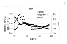 |
| 5508614 | 4-Jun-2014 13-Mar-2009 |
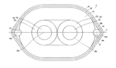
HIGH-SPEED DIFFERENTIAL CABLE | PROBLEM TO BE SOLVED To provide a high-speed differential cable excellent in transmission characteristics. SOLUTION In the high-speed differential cable 1, two signal lines are arranged in parallel as two cores and with a first dielectric layer 12 provided on an outer periphery of an internal conductor 11, a second dielectric layer 13 is provided on an outer periphery of the two-core signal lines, drain lines 14 are arranged in parallel with a signal line on either side of the two-core signal lines to be outside the second dielectric layer, an outer conductor 15 with an insulation side to be outside and a conductor to be inside is provided vertically on an outer periphery of the second dielectric layer and the drain line, an outer cover 16 is provided on an outer periphery of the outer conductor, and a groove part 17 for a drain line, insertion-coupled with at least a part of a circumference of the drain line, is provided in an outer peripheral part of the second dielectric layer with the drain line arranged. Hence, the signal line and the drain line are precisely arranged in symmetry, an electric balance of the two cores of the sinal line are electrically well balanced, and therefore, excellent electric characteristics and transmission characteristics are obtained. Since the outer conductor is provided vertically, generation of sack-out of attenuation in a high-frequency region is prevented. |
 |
| 5477938 | 23-Apr-2014 9-Jun-2008 |
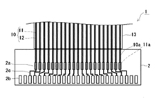
FLAT CABLE | PROBLEM TO BE SOLVED To provide a flat cable capable of preventing the snapping of an internal conductor in the vicinity of an electrical connection section with a base plate even though stress is added on the internal conductor of the cable to be connected, with the base plate in a cable thickness direction and in the cable width direction. SOLUTION The flat cable 1, wherein a plurality of cables 10 are arranged in parallel, is covered with an insulating material 13, the tips of the internal conductors 11 of the cables are electrically connected with terminals 2a of the base plate 2, and the plurality of cables are exposed so as to have designated peeling-off length from an end of the insulating material by peeling off the insulating material in the vicinity of the connection section. Thus, the plurality of cables in the vicinity of the connection section can be relatively separated from each other; the stress can be dispersed to respective cables in the vicinity of the connection section even though the stress is added on the flat cable in the cable thickness direction and in the cable width direction; and the snapping of the internal conductor can be prevented. Then, rough handling can be permitted at cable wiring, and a wiring operation is facilitated. |
 |
| 5469858 | 16-Apr-2014 24-Dec-2008 |
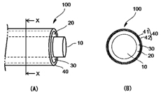
ROLL COVER | PROBLEM TO BE SOLVED To provide an inexpensive roll cover having high adhesive property to a roll body. SOLUTION The roll cover 40 includes at least a first layer 41 formed of thermoplastic fluororesin that does not contain an adhesive functional group, and a second layer 42 formed of thermoplastic fluororesin that contains an adhesive functional group on an inner peripheral surface of the first layer. At least an inner peripheral surface of the second layer is treated with an ultraviolet ray made to irradiate the outside of the first layer. Thus, the adhesive functional group contained in the second layer of the roll cover composed of the thermoplastic fluororesin is activated by ultraviolet ray irradiation, so that the roll cover including the second layer having the high adhesive property to the roll body is obtained. Since the outside of the first layer which forms an outer layer of the roll cover has only to be irradiated with the ultraviolet ray, treatment of the roll cover from molding treatment to surface treatment can be performed continuously consistently, thereby achieving the reduction of cost of the roll cover. |
 |
| 5443794 | 19-Mar-2014 13-Mar-2009 |
HIGH-SPEED DIFFERENTIAL CABLE | PROBLEM TO BE SOLVED To provide a high-speed differential cable excellent in transmission characteristics. SOLUTION In the high-speed differential cable 1, two signal lines 10 are arranged in parallel as two cores and with a first dielectric layer 12 fitted on an outer periphery of an internal conductor 11, a first outer conductor 13 with a conductor side to be outside and an insulation side to be inside is provided on an outer periphery of two-core signal lines, a drain line 14 is arranged in parallel with a signal line on one side of the two-core signal lines to be outside of the first outer conductor, a second outer conductor 15 is provided on an outer periphery of the first outer conductor and the drain line same as the first outer conductor, and an outer cover 16 is provided on an outer periphery of the second outer conductor. The two-core signal lines are covered with an insulation side of an inner side of a first outer conductive layer, and the drain line is in contact with a conductor side of an outer side of the first outer conductive layer, thus a conductive potential having potential difference between two-core signal lines is not introduced to the first outer conductor so as to reduce loss by restraining electric current generated on the first outer conductor, degradation of attenuation is suppressed. Skew is also reduced by enhancing a binding degree of a pair of internal conductors. |
 |
| 5416432 | 12-Feb-2014 24-Feb-2009 |
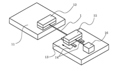
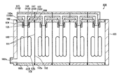
DEAERATOR | PROBLEM TO BE SOLVED To provide a deaerator which can easily change the deaeration treatment amount of liquid at a low cost, occupies a small space, and facilitates installation of vacuum piping. SOLUTION The deaerator 100 includes a deaerator unit 101 comprising a reducing chamber 110 having openings 111, 112 disposed in two sites, a first sealing member 102 provided with a vacuum suction opening 102a to seal the opening 111, and a second sealing member 103 for sealing the opening 112. The number of arranged deaeration units can be increased and decreased according to the deaeration treatment amount of liquid. As a result, it is structured that one vacuum chamber is provided with one vacuum suction opening, whereby the installation of the vacuum piping can be simplified and the occupation space can be made small, and it is structured that the number of the arranged deaeration units can be easily increased and decreased, whereby coping with a change in the deaeration treatment amount of liquid can be easily performed without requiring time and labor, and cost. |
 |
| 5369217 | 18-Dec-2013 25-Apr-2012 |
FLUORORESIN COMPOSITION | PROBLEM TO BE SOLVED To provide a fluororesin composition having a low electrostatic propensity; and to provide a fluororesin molded article having a low electrostatic propensity that is configured from a fluororesin composition. SOLUTION A thermoplastic fluororesin composition comprises a fluororesin, two or more of vinylidene fluoride-tetrafluoroethylene-hexafluoropropylene terpolymers and an ionic liquid, wherein the terpolymers include a terpolymer selected from terpolymers containing 30-45 mol% of vinylidene fluoride and a terpolymer selected from terpolymers containing 5-25 mol% of vinylidene fluoride. A fluororesin molded article is also provided. |
